
MGSE© REC/REP V2.0
Mobile Record & Replay Unit for all GNSS Bands

Background
During GNSS receiver development, qualification, and certification phase every stakeholder wants to optimize resources and time. This can be achieved by selecting the optimal test and simulation system or combinations of them.
MGSE© REC/REP 2.0 creates a GNSS simulation environment that provides the possibility and flexibility to use recorded real-world samples which can be replayed exactly reproducible. Such a tool considerably improves the development, qualification, and certification process of GNSS receivers within development phases and for the validation/certification in end-to-end tests. MGSE© REC/REP 2.0 is addressing the testing of complex multi-system, multi-signal devices and other receivers used in an ever increasing range of commercial and governmental applications.
In the GNSS testing markets, applications will grow for multi-GNSS technologies, such as BeiDou with GPS, Galileo, and GLONASS. These are significant drivers for both governmental and commercial customers, including the emerging “wearables” technology sector. The growing concern over the vulnerability of GNSS receivers to interference, including jamming and spoofing, is becoming an important market driver as well.
System Description
The MGSE© 2.0 system consists of two elements:
MGSE© 2.0 Recording Unit: Provides received and recorded real-world GNSS data
MGSE© 2.0 Replaying Unit: Provides replayed digital GNSS IF and/or analog RF data
MGSE© 2.0 Recording Unit (MGSE© 2.0 REC)
Beside the multi-band GNSS antenna, the main objective of the (MGSE© 2.0 REC) is to receive the RF signal, to filter and amplify the incoming signal in different frequency bands simultaneously and then to down-convert and quantize the signals, in order to obtain digital intermediate-frequency forms, which can be used by the actual receiver.
The MGSE© GTEC© 2.0 REC subsystem includes a new reception board to receive and process the IRNSS S-band in addition to the already available other frequency L-band combinations.
MGSE© Replaying Unit (MGSE© 2.0 REP)
Recorded real-world GNSS data can be replayed either as digital IF GNSS signals or as analog RF multi-band data in real-time to receivers / components under test.
The MGSE© 2.0 REP includes a flexible multi-band, USB3.0 digital and analog RF replay device, that can stream MGSE© REC recorded raw IF data to a digital baseband output or to an analog RF signal.
MGSE© 2.0 REP simultaneously supports up to two independent RF channels and up to four GNSS signals e.g. L1, E1, B1, G1 per channel.
The MGSE© 2.0 REP can also replay synthetically generated IF data which are e.g. generated by a GNSS software signal generator in the lab.
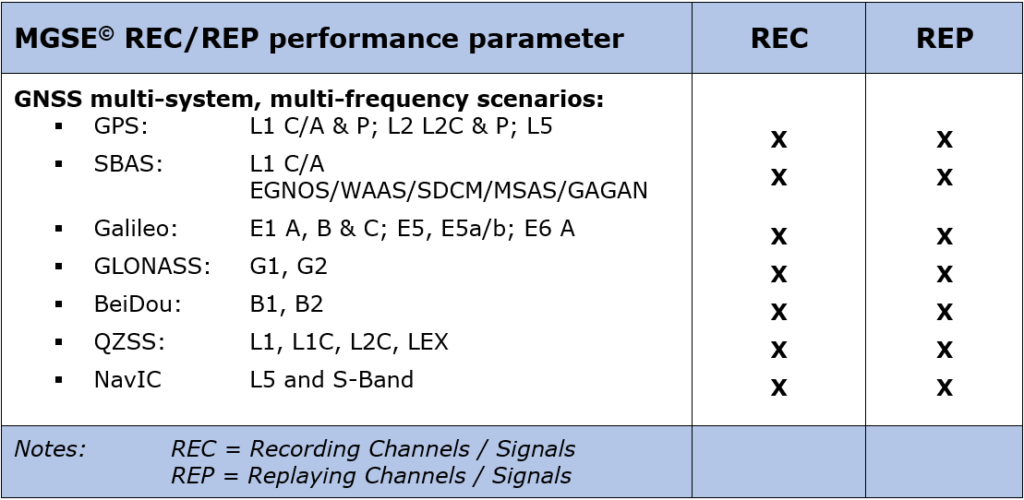
The key design characteristics of MGSE© V2.0 are listed below:
Application examples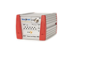
- – Development of software defined radios/receivers (SDR)
- – GNSS multi-system signal analysis and comparison
- – Analysis of atmospheric effects, e.g. iono-/ tropospheric irregularities, scintillation etc.
- – Interference monitoring for protecting critical infrastructures
- – Beamforming
- – GNSS multi-system, multi-band receiver performance testing
- – Jamming and spoofing test and evaluation
- – Mobile testing of GNSS receivers embedded in application platforms (e.g. vehicles, tractors, etc.)
Technical details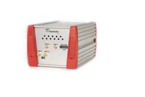
- – Dimensions (L/W/H): 188/125/100 mm, weight: 1.6 kg
- – High stability internal reference oscillator (OCXO)
- – Super speed USB 3.0 (up to approx. 1.3 Gbit/s)
- – Large FPGA (Xilinx Spartan7) for signal conditioning and algorithms
- – USB driver with application programming interface (API)
- – Supporting the ION Metadata Standard
- – GUI for visualization, record and replay included
- – Drivers for Windows 7/10 and Linux
Interfaces
- – REC: up to three antenna inputs
- – REC: antenna supply with a maximum of 70 mA at 4.3 VDC
- – REC: parallel digital data output (optional)
- – REC: u-blox ubx embedded as internal reference (optional)
- – REP: RF signal output
- – REC/REP: 10 MHz Reference clock input and output
- – REC/REP: Trigger in/out